Results and Discussion
Aerodynamic Boundary Determination
Within the realm of sail dynamics and the traditional concepts of sail mechanisms, it is a common analogy to liken the shape of a sail to that of an airplane wing, as sails embody the characteristics of a thin, flexible, cambered airfoil. Cambered airfoils are distinct in their lift-generating capabilities, often outperforming their symmetric counterparts by producing significant lift at lower angles of attack, and some designs are even capable of generating lift when oriented directly into the wind. This comparison, however, must account for the critical distinction that sails, unlike airplane wings, are not rigid structures. As a result, sails demand a minimum angle of attack to ensure a higher pressure on the windward side than on the leeward side to sustain the sail's curvature. Without this pressure differential, a sail cannot uphold its cambered form and will shake, or luff as shown in figure 5.
The objective of the initial simulation was to evaluate the mainsail's aerodynamic properties in isolation, to identify the lower limit angle of attack that maintains sail shape and to determine the angle that maximizes the driving force coefficient. As outlined in the methods section, the sail was modeled as a rigid structure in these simulations. This is a critical consideration, as it necessitates a close examination of the pressure at the leading edge of the sail to establish a lower boundary supporting designed sail shape. This threshold is essential for determining the minimum AoA at which, under actual sailing conditions, the chosen sail geometry would retain its shape, thus enabling a realistic and focused investigation into the sail's intrinsic aerodynamic characteristics.
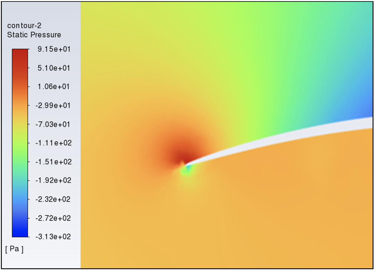
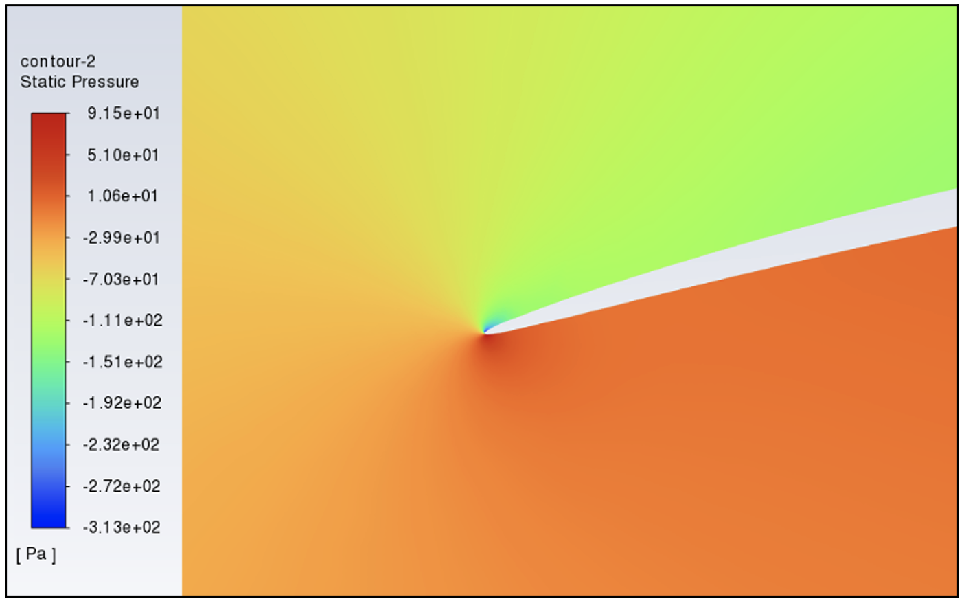
The analysis commenced with observing the pressure contours at the sail's leading edge, starting from an angle of attack of 0 degrees and advancing in increments to 10 degrees. From 0 - 7.5 degrees, the sail’s pressure profile would struggle to sustain a proper aerodynamic shape due to insufficient pressure differential, as evidenced by the figure 16. Conversely, at an angle of 10 degrees, the pressure on the windward side was adequately higher, allowing the sail to preserve its shape effectively, as shown in figure 17.
Figure 16: Pressure Contour at 7.5º AoA
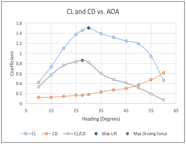
With the lower angle of attack boundary established, the sail's performance was evaluated at angles from 10 to 60 degrees, in 5-degree steps. The lift coefficient (CL) and drag coefficient (CD), along with their ratio defining the driving force coefficient, were calculated. The resulting graph (Figure 18) displays these coefficients across the range of angles tested. Notably, while the maximum lift occurs at 30 degrees, the peak driving force coefficient is achieved at 27.5 degrees, signifying the most efficient angle for sail propulsion. This slight reduction in the angle not only increases speed but also reduces the distance needed to reach the desired course, underlining the importance of optimizing the angle of attack for both speed and course efficiency, the all-important VMG in sailing racing.
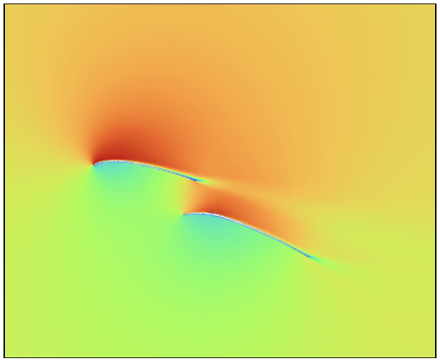
For the traditionally taught theory to hold, the accelerated flow in the slot between the mainsail and jib would result in a corresponding increase in velocity on the jib's windward side. This would result in more lift for the mainsail but a decrease in lift for the jib. Yet, Figure 26 reveals no such increase in velocity but rather a decrease over the mainsail showing evidence that the jib is generating most of the lift from the combined sails.
Figure 27 illustrates the pressure distribution across the jib's leading edge at a 7.5-degree angle of attack. The windward side exhibits a higher pressure than the leeward side, suggesting that even at this angle to the wind (AoA), the jib can maintain its designed shape when function in tandem with the mainsail. This is in stark contrast to the mainsail operating alone, which requires a minimum of 10 degrees of angle to avoid luffing (loss of cambered shape), as established by the initial simulations.
Figure 27: Pressure Contour of Jib at 7.5º AoA
As explained in the introduction, circulation is a flow pattern that wraps around an airfoil, creating a rotational movement in the air [2]. When the jib and mainsail are both present, their circulation fields interact, as shown in Figure 30. The figure illustrates the counter-rotating circulation patterns around both the jib and mainsail.
The opposing circulations in the slot, the area between the jib and mainsail, slow down the flow’s velocity. The jib's circulation reduces the velocity of the air passing through the slot, which, according to Bernoulli's principle, causes the pressure in the slot to increase. At steep angles of attack, low pressure near the leading edge gives way to increasing pressure towards the trailing edge. This pressure gradient intensifies with the angle of attack, heightening the risk of flow separation. Therefore, this increase of pressure at the mainsail’s leading edge, due to the circulation in the slot, helps decrease this pressure gradient and beneficially reduces the risk of flow separation.
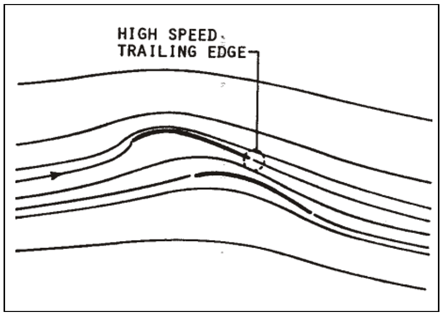
As established earlier, the Kutta condition necessitates that airflow exits the jib's trailing edge seamlessly, a scenario facilitated by the high-speed airstream created by the mainsail's presence. This interaction is depicted in Figure 33, where the mainsail's flow field boosts the velocity around the jib, ensuring the Kutta condition is met. Consequently, this effect, combined with the converging circulations from Figure 30, leads to increase velocity and decreased pressure on the leeward side of the jib, thereby increasing its lift and efficiency in another way.
The interactions between the jib and mainsail discovered in the simulations paint a detailed picture of the intricate aerodynamics at play when sailing. For the jib, three key effects emerge from the combination of the sails:
Figure 18: Sail Performance vs. Heading
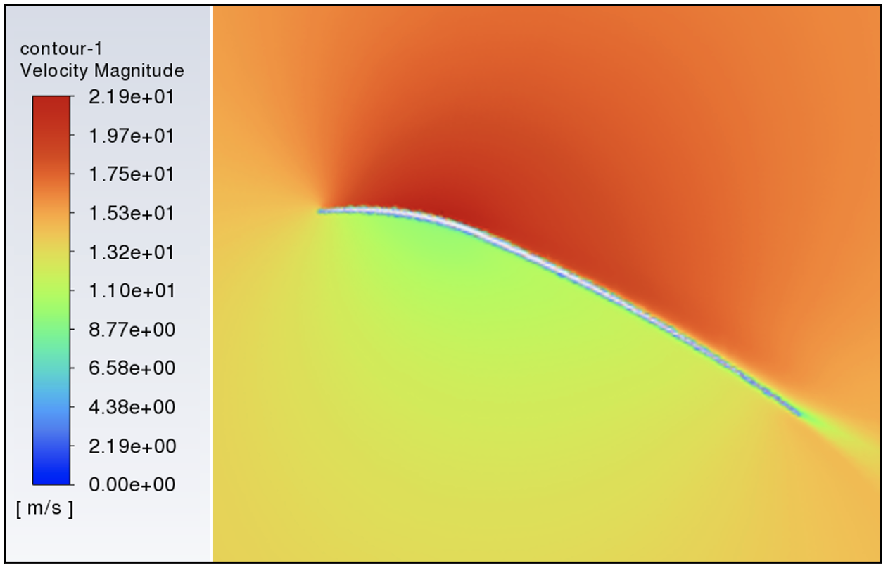
To further validate these numerical results, velocity contours were evaluated at key angles. The contour at 25 degrees (Figure 19) indicates a smooth, attached flow, revealing efficient lift generation. As the angle of attack increases to 35 degrees (Figure 20), the contour begins to depict flow separation, corresponding to the observed elevation in drag and reduction in driving force on the graph (Figure 18). At 60 degrees (Figure 21), the contour clearly illustrates a stall with severe airflow detachment, confirming the steep rise in drag and plummeting lift as indicated in figure 18.
Figure 19: Velocity Contour at 25º AoA
Mainsail and Foresail Interaction
Sail Configuration Comparison
Figure 17: Pressure Contour at 10º AoA
Figure 20: Velocity Contour at 35º AoA
Figure 21: Velocity Contour at 60º AoA
In the realm of fluid dynamics, this behavior aligns with established principles. At low angles of attack, the airflow remains attached to the sail, maintaining higher lift and lower drag, conducive to efficient sailing. As the angle of attack increases, the flow begins to separate, incrementally at first, then more drastically, culminating in a stall characterized by a significant loss of lift and a spike in drag. These phenomena are crucial for sailors to understand as they directly impact sail trim and strategy during a race. Indeed, tuffs of wool first proposed by Gentry [12] as indicators of stagnation point location and airflow at the trailing edge, are now universally used in modern racing sailboats.
The first simulation's results have thus established an effective operational range of 20 to 35 degrees, which will guide the exploration in the upcoming simulations. This selected range encompasses the angles at which the sail demonstrates optimal aerodynamic efficiency and sets a solid foundation for comparing the performance of different sail configurations, ensuring that the follow-up studies are focused on the sail's most relevant data.
The second simulation was conducted to examine the interaction between the mainsail and foresail across a range of angles of attack. This investigation holds significant importance in the realm of sailing theory and sail design, as it challenges and re-examines traditional beliefs.
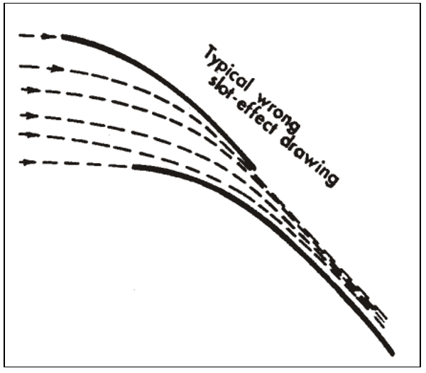
One of the most prevalent but errant traditional theories in sailing literature suggests that the jib, by channeling air, increases the wind velocity on the leeward side of the mainsail, thereby increasing lift (Figure 22) [13]. This concept, while capturing a facet of the interaction, is found to be an oversimplified representation when juxtaposed with the findings from these simulations and real-world conditions.
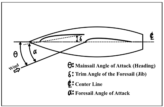
Figure 23 presents a diagram detailing the configuration of the mainsail and jib on a typical boat. The foresail (jib) trim angle (δ) is defined as the angle the jib creates with the boat's centerline. It's crucial to recognize that the mainsail is set in alignment with the centerline, thereby equating the mainsail's angle of attack to the boat's heading, represented by θ. This figure demonstrates that as the jib trim angle (δ) widens, there is a decrease in the foresail's angle of attack (α), a pivotal consideration when tuning the sails for optimal performance
By adjusting the mainsail (or boat’s) heading from 20º to 35º in increments of 2.5º and varying the foresail trim angle from 7.5º to 20º, a comprehensive study of driving force coefficients in relation to foresail trim was achieved.
Figure 24: Impact of Foresail Trim
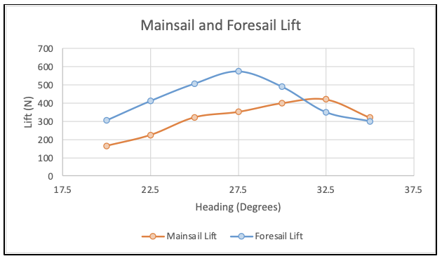
Figure 25: Mainsail and Foresail Lift
Figure 32 shows the jib streamlines with(solid) and without(dotted) the mainsail. Sj0 is the stagnation streamline of the jib without the mainsail and Sj is the jib’s stagnation streamline with the mainsail. The distance between the two, L is the amount of air that is now diverted over the leeward side of the jib with the mainsail in place. This additional airflow shown in both figure 31 and 32 serves to increase the leeward flow velocity and moreover, in front of the jib, the two circulations, as seen in Figure 30, add together. This combined effect increases the upwash at the leading edge of the jib. This is why, as per the simulation results, the jib can generate more lift at lower angles of attack (Figure 25) and why the boat can be pointed closer to the wind without the risk of the jib luffing (Figure 27).
Figure 22: Traditional “Slot-Effect” Theory [14]
Figure 23: Mainsail and Jib Configuration
The first graph presented (Figure 24) shows the driving force coefficient at three specific headings: 20º, 22.5º, and 25º, against the foresail trim angle. This selection of headings was intentional to avoid cluttering the graph and to highlight the trend that as the heading (mainsail) angle increases, the optimal foresail trim also increases. At a 20-degree mainsail angle, the jib exhibits peak performance when trimmed closer to the centerline (decreased angle of attack), with increased trim angles (higher angle of attack) resulting in diminishing efficiency. Contrastingly, as the mainsail angle widens to 25 degrees, the jib’s most efficient trim angle shifts outward; the largest 20-degree trim now surpasses a 7.5-degree setting in driving force generation. Consequently, this implies that while sailing closer to the wind, a snugger jib trim prevails, yet as the course bears away, a broader jib trim proves to be more advantageous. However, it is important to note that the most efficient jib trim, shown with the trend line, which remains between 10 and 12.5 degrees defines the distance of the slot in between the jib and the mainsail. If the traditionally taught theory was correct, then the jib would perform better at smaller trim angles regardless of mainsail angle of attack. However, that is not the case.
The lift produced by both the mainsail and foresail at various headings (mainsail AoA) is shown in figure 25. The optimal foresail trim angle's lift values at varying mainsail AoA, or headings, were utilized to understand how each sail functions across the different headings. Notably, the foresail demonstrates higher lift than the mainsail when the boat sails closer to the wind, which is visually supported by the velocity contour of both sails (Figure 26). The local velocity over the foresail is noticeably higher than that over the mainsail, indicating a more efficient operation despite its smaller size and lower angle of attack (figures 25 and 26). From the previous simulation, the mainsail operating alone achieved maximum lift at a 30-degree angle of attack and in contrast, when the jib and the mainsail are operating in tandem the jib reaches maximum lift at 27.5 degrees and when the mainsail reaches maximum lift at 32.5 degrees. Therefore, it follows that the flow interaction between the two sails allows the jib to function effectively at lower angles of attack and allows the mainsail to function effectively at higher angles of attack when compared to the single sail arrangement
Figure 26: Velocity Contour at 20º AoA
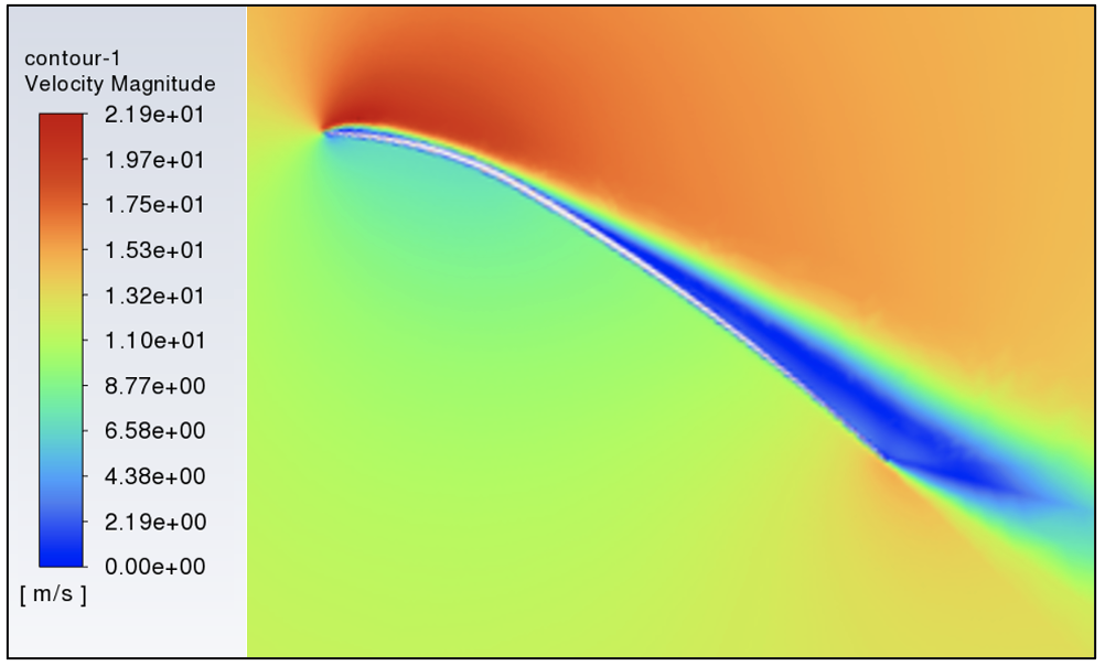
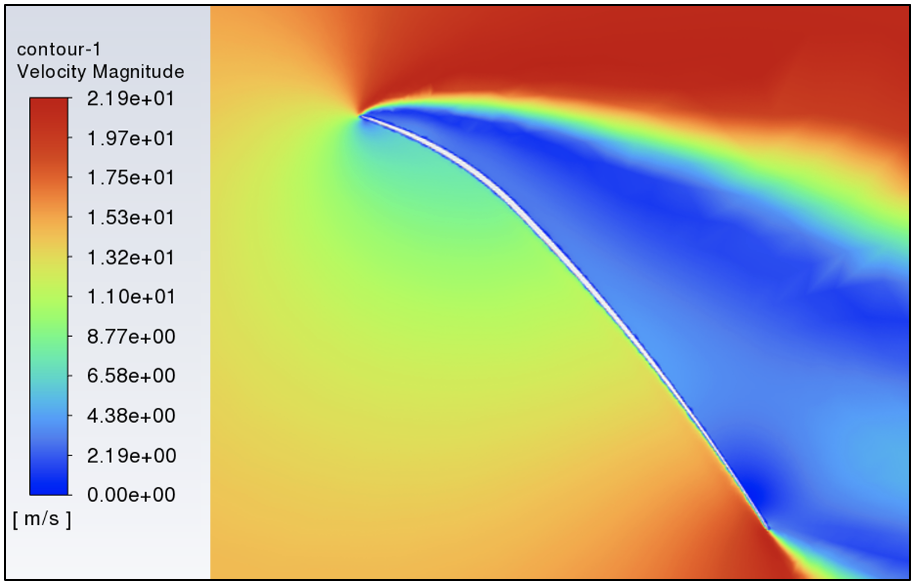
The velocity contours over the mainsail when operating with (Figure 28) and without the jib (Figure 29) further indicate that the mainsail can function more effectively at higher angles of attack in the presence of the jib. The flow over the leeward side of the mainsail in figure 28 is slower than the flow over the mainsail in figure 29, which according to Bernoulli’s principle (1), increases the pressure at the leading edge of the mainsail. This reduces the pressure gradient on the leeward side from the leading edge to the trailing edge thus reducing the size of the boundary layer and reducing the flow separation as shown. Moreover, this directly disproves the common misconception that the “slot effect” increases the velocity over the leeward side of the mainsail.
Figure 28: Velocity Contour at 35º AoA with Jib
The traditional “slot effect” theory would lead us to expect that tightening the jib narrows the slot between the sails and accelerates the airflow, thereby lowering the pressure on the leeward side of the mainsail (Figure 29). Yet, the common experience of backwinding – a condition where the sail luffs due to the jib being over trimmed - suggests otherwise, indicating that the pressure differential across the mainsail does not increase as anticipated, but rather decreases as would happen if the leeward flow was decelerated.
In essence, the combined operation of the jib and mainsail accomplishes several feats: it allows the jib to sail closer to the wind (lower AoA), while still holding is curvature, increases its leeward velocity for more efficient jib lift generation, decreases leeward velocity on the mainsail to reduce the risk of flow separation, and enables the mainsail to attain higher angles before stalling. These findings challenge the traditional slot effect theory, leading us to a deeper discussion of the aerodynamic principles that underpin the observed behaviors in the simulations.
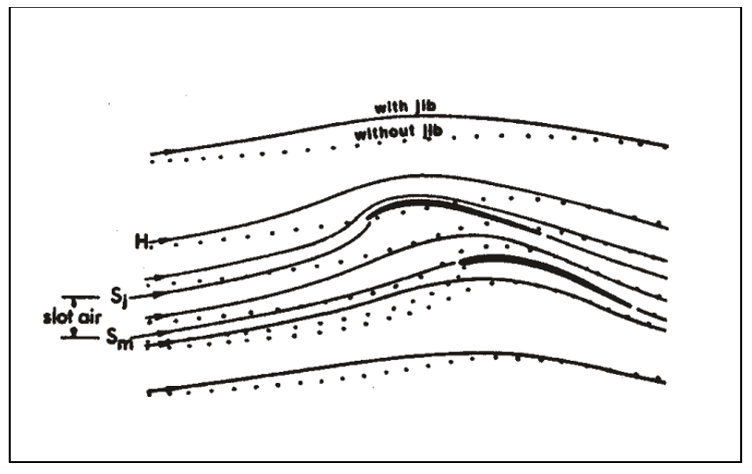
Figure 31: Mainsail Streamlines with/without Jib [14]
Figure 31 shows theoretical streamlines around the mainsail with (solid) and without the jib (dotted). The H is the dotted streamline which depicts the stagnation streamline of the headstay, where the jib normally attaches to the boat. When the mainsail is operating without the jib, the distance between Sm, the mainsail stagnation streamline, and H is the amount of air that passes through the slot. When the jib is added, the amount of air that passes through the slot decreases as some of it is diverted over the leeside of the jib because of the incidence of the jib’s stagnation point and its consequent upwash, the upward movement of airflow on the leading edge of a sail. This in turn also affects the mainsail’s stagnation point incidence and decreases the amount of upwash at the leading edge of the mainsail, effectively decreasing the angle of attack without changing the actual angle of the sail (or boat heading). This in combination with the counter rotating circulation decreases the speed of the flow around the leading edge of the mainsail and reduces the likelihood of flow separation. This was shown in the simulation results, through the maximum lift achieved by the mainsail at 32.5 degrees in figure 25, and visually in figures 28 and 29.
1. The combination of circulations of the two sails, increase the upwash at the leading edge, effectively increasing the angle of attack of the oncoming air without increasing the actual angle of the sail.
2. The increased flow over the jib's leeward side accelerates the air, reducing pressure and thus increasing the jib's lift.
3. The jib's trailing edge benefits from the mainsail's faster downstream air, satisfying the Kutta condition at elevated speeds. This phenomenon not only assures smoother airflow but also raises the velocity across the jib's leeward surface.
In a third simulation, the performance of a hypothetical larger mainsail was evaluated against the two-sail configuration established in previous simulations, refer to figure 6. Comparing the performance of a two-sail configuration to that of a hypothetical larger mainsail is important as it offers insights into the evolution of sail design, especially considering that historically, many sailing vessels relied on a single primary sail. This comparison helps to quantify the benefits of modern sailing tactics that utilize both a mainsail and a jib, demonstrating the technological and strategic advancements in sailing that enable higher efficiency and better performance. The comparative analysis of the two-sail arrangement and a larger area mainsail, as described in the methods, was conducted across the functional range of 20 to 35 degrees in 2.5-degree increments, as identified in the first simulation. The graph (Figure 34) for this simulation overlays the total lift and driving force coefficient generated by both the larger single mainsail and the combination of mainsail and jib. This direct comparison elucidates the relative efficiencies of the two different sail configurations under identical conditions.
Figure 29: Velocity Contour at 35º AoA without Jib
Figure 30: Sail Circulation Interaction [12]
Figure 32: Jib Streamlines with/without Mainsail [15]
Figure 33: Two Sail Configuration Streamlines [15]
For the mainsail, the results are equally significant:
1. The opposing circulations in the slot between the sails decrease velocity at the mainsail's leading edge, thus increasing pressure.
2. This pressure boost, coupled with the jib's dampening effect on upwash, diminishes boundary layer separation on the mainsail.
These effects explain the jib’s ability to produce more lift (Figures 25 and 26) and point higher into the wind without luffing (Figure 27). This allows the boat to sail a tighter course to the wind, which can be the difference between winning and losing when sailing upwind legs in a race. This advantage is crucial when trying to maintain an advantageous position relative to competitors and the wind. These effects also explain how the mainsail can sustain higher angles of attack without stalling (Figures 25, 28 and 29) which allows for a broader range of efficient sailing angles. This means that the boat can be sailed more aggressively in various wind conditions without the loss of speed and maneuverability that comes when the sails stall. This capability is particularly useful when dealing with shifting wind conditions or when needing to accelerate quickly.
Figure 34: Comparative Analyses of Dual-Sail Configuration versus Single-Sail Configuration
In analyzing the performance of sail configurations, Figure 28 shows that a two-sail arrangement, comprising a mainsail and a jib, yields higher lift across VMG-crucial angles of attack—specifically from 20 to 30 degrees—when compared to a larger mainsail covering an equivalent area. This observation aligns with the enhanced efficiency and lift generation attributable to the jib, as identified in the previous simulations.
This analysis emphasizes that the two-sail arrangement not only generates more lift but does so at a reduced angle of attack. With an optimal driving force coefficient of 9.04 at 25 degrees for the two-sail setup—outperforming the larger mainsail's 8.62 at 27.5 degrees by almost 5%— it's clear that the inclusion of a jib, even with the same total sail area, is more advantageous than a single larger mainsail.
Extrapolating these findings to a typical one-mile race with two upwind legs reveals that the two-sail configuration would sail 0.04 miles less distance, thanks to its ability to point higher into the wind (reduced AoA). This is a significant strategic advantage, and the additional driving force translates to a 4.87% increase in speed. Furthermore, should one opt to match the speed of the larger mainsail-equipped vessel, the two-sail configuration could afford to sail nearly 5 degrees closer to the wind, which would result in a 0.085-mile shorter course. In the fiercely competitive realm of sail racing, where the margin between victory and defeat is often measured in mere seconds, even a seemingly modest improvement in performance can be pivotal. Thus, the combined gains from a slight percentage increase in speed and a minor reduction in the distance sailed, as afforded by the two-sail configuration, could very well be the deciding factor that distinguishes the frontrunner from the rest of the pack. Such insights underscore the critical role of sail configuration in racing tactics, where the balance of speed and course efficiency is paramount.
The simplifications undertaken in this computational sailing study, while necessary to contain the scope within manageable parameters, have several implications for the real-world applicability of the results. By employing a 2D cross-sectional analysis, the study bypasses the more nuanced behaviors of three-dimensional airflows, such as those interacting with the mast and sail edges. These elements can introduce vortices and affect flow attachment, potentially altering sail performance in ways not captured by the model.
Neglecting the mast geometry similarly streamlines the simulations but omits the mast's aerodynamic impact. The mast's presence can induce flow separation and turbulence, intricacies that sailors often counteract through precise trim adjustments. Consequently, the absence of the mast in the simulations may result in an optimistic portrayal of sail efficiency, with a possible overestimation especially for the mainsail.
The alignment of the mainsail with the boat's centerline, while isolating angle of attack effects, does not reflect the dynamic trimming actions required in response to changing wind angles in active sailing scenarios. Thus, the optimal angles identified through the study may not directly translate to the most effective sailing angles in varied conditions where sail adjustments are a constant.
Considering the vessel speed to be below hull speed focuses the analysis on aerodynamic efficiency without accounting for hydrodynamic resistance that becomes significant at higher speeds. Such resistance, alongside the boat's heel and the drag from hull, keel, and rudder, would affect the boat's velocity and consequently, the VMG, which is central to racing strategy.
The assumption of a constant apparent wind velocity negates the variable nature of wind experienced in sailing, where shifts and interactions between the boat's motion and true wind significantly impact performance. This simplification could lead to different conclusions regarding sail efficiency compared to an environment where apparent wind varies with the boat's progress.
Lastly, the study does not incorporate VMG optimization, a pivotal concept in competitive sailing, which directly influences course setting and sail trim decisions. This omission suggests that the study's findings may not fully align with the tactics and outcomes of actual sail racing, where optimizing VMG is key to minimizing distance and maximizing speed toward an upwind mark.
While the study provides valuable insights into the aerodynamic effects of sail angles and interactions, its findings are indicative of performance trends rather than definitive outcomes. They underscore the need for further research involving three-dimensional models and empirical data to capture the complexities of sail interactions more accurately under varied wind conditions and dynamic sailing maneuvers.
